
Reset and automatic close Windows
see here if windows fail to move
This can be necessary if, when the window is open and you try to raise it, it goes up but then comes back down to the half way point again. The only way to keep it at the top it to edge it up bit by bit and not fully close it.
As on any Peugeot/Citroen, it needs to relearn the end-positions. When the window is closing, the window ECU stops if there is a finger in the way and immediately lowers the window again to avoid injury.
The solution is to lower the window with the switch, and maintain pressure on the switch a few seconds longer so it can relearn the "down" position. Then raise the window and again keep the switch in the up position a few seconds longer to relearn the "up" position.
If the window is sticky in the guides - check there is no debris in the guides or channel at the top and apply some thin silicone oil to the guides.
Window motor wiring
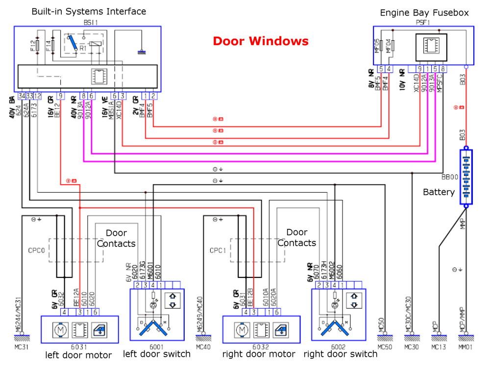
this is the wiring diagram for the windows
Automatic windows
The windows can be made to close automatically when the doors close: this suggestion from József Svégel
Peugeot 1007 comfort window control module construction and installation
One of the shortcomings of the Peugeot 1007 is that, even though the windows have the option of automatically winding up, the windows do not close when the doors are closed, nor can they be forced to close as part of the factory standard equipment.
This error was not eliminated in the nest lift version either, although we suspect that the ECU program could have this convenience function by modifying a few lines. Why this was left out of the development of French engineers remains an eternal mystery.
But the problem is there, because the window that remains open can only be rolled up if we open the door again, get in, turn on the ignition and close the door again, because only then is the line of contacts at the top of the doors connected. This is more than inconvenient, and the passenger side window can even remain down, as the driver does not always see it when he leaves the car alone.
In the lines below, we outline the operation of the new window winder module and the installation details.
You should know about the 1007 window regulator system that 4 wires are connected to the buttons in the center console as buttons. The question is how it is possible to pull up, pull down, automatically pull up, automatically pull down, and operate the built-in lighting with so few wires. As you can feel, by gently pressing the button, the window moves as long as you keep the button pressed. If you push it beyond the perceptible click, it switches to automatic mode, i.e. it moves the window completely down or up.
The assignment of the 4 wires is as follows: +12V, this is what lights up the switch, and the button sends this voltage to the factory window modules, which are in the doors, of course one on each side. There is a body thread, this gives the built-in LED the body, and the remaining two threads are up and down.
The question is, how does the window module know that there is only a momentary button press, or automatic mode with overclicking. The solution is simple. For example, if I want to pull up a window, I pull up the button. Then the button sends a signal to the window module on the "up" wire, and it starts to move the window up. If you drag the button too far, the module receives the "down" signal in addition to the active "up" thread, which it interprets as switching to automatic mode. In other words, the window module can receive 4 types of signals from the button, single up, single down, up and then immediately down, finally down and immediately up. These are handled by the physical design of the buttons.
In other words, our new module must imitate the operation of the button, it must give a signal to the "up" thread, and then after a few tenths of a second to the "down" thread, so the window module feels that we wanted automatic up mode. And that's exactly what we need.
The start signal itself doesn't have to be high current, it's just a pulse to the window module, just signal-level voltage without actual current. Since the comfort winding must be triggered by closing the car, it is logical that we have to use the voltage coming to the central lock for this. We have to put this signal on the "up" thread, then delay it by a few tenths on the "down" thread and our window will go up in automatic mode. The stop of the raised window in the closed position is handled by the end position and overcurrent protection of the window module itself.
After all this theory, let's see the practical implementation. Of course, we have to tap the wiring system of the car to have a central locking signal. The most suitable place for this is the door contact, because there we have all the signals we need. This is held by a torx screw and can then be turned out of the body.
Since the pin assignment of the left and right-hand drive versions may differ, we need to highlight this. Connect the negative of the test lamp to the body, the positive to one of the plates of the contact row, then try to lock the car with the button on the center console (not the door!), and with a few tries you can find the right wire from which you can connect the lock signal. We remove the bandage from the wire, strip the insulation on a small piece, and with the method of screwing it on and soldering it on, we already have a signal. Of course, make sure to carefully insulate and not to cut the wire, just strip it carefully. We have to look for a body thread in the same place, it is always green/yellow, there is no need to light it. These must be introduced into the passenger compartment, luckily this can be easily done by routing the original cable harness.
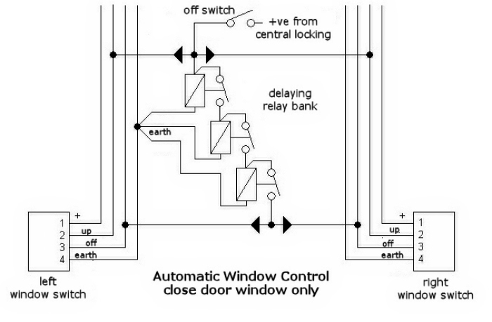
These will be the input wires of our module, and the outputs will be connected to the wires of the original switches, as shown in the figure. We route the central locking signal through a switch, as it may be necessary for our new function to not work, for example, if an animal stays in the car, or if something goes wrong, the new module can be disabled. The switch can be installed anywhere, even hidden, as long as we know about it.
The incoming (by the way, approx. 1 second) pulse enters the "up" wires through the two diodes pointing towards each other, the windows start to go up when the door is closed. The uppermost relay receives a signal and pulls in late, since the moving parts of the relay need time to close. Then the second relay receives a signal, which is also delayed, then the third, and finally the delayed signal appears on its output, which is applied to the "down" threads, which the window module perceives as a command to automatically wind up. The role of the relays is that the three together approx. delay the signal by 3 tenths of a second. The diodes prevent the switches' circuits from interacting during normal operation.
The wires coming from the diodes must be connected to the wires of the original switches. Unfortunately, these are very thin threads, you need some patience to tie them on. It is worth unclipping the window switches from the center console and connecting them there. The 4 wires of the switch must be measured. The green/yellow body, one of them is the constant 12V, the rest is up and down. Some guesswork is required as color codes may vary. Another option is to look for the "up" and "down" wires of the window on the door's inverted contact line, since the buttons send the signal to the modules in the doors. Of course, the left window can be controlled in the left-hand door, and the right window can be controlled in the right-hand door, so the signal from the new module must be routed to both door contacts.
If, during the test, the windows open in one of the opposite directions, the two wires must be swapped. The module can be placed as desired, but we think that the central lock, the body, its own switch, and finally the window lifter switches can be connected to it. Mine is located behind the removable plastic plate under the steering column.
It occurred to me that if we could roll up the window, there could be a function so that the windows could be rolled down in the summer heat, not just up. In other words, if I open the central lock (not the door, since the edge of the door must touch), the windows will go down. Since this can only be used in hot weather, the module itself and the summer function must be separately switchable. This is why the following connection was born.
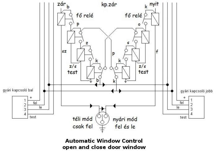
Here we are talking about the fact that the switching is doubled, there is a pull-up side consisting of a relay stage and an equally pull-down side. The row of relays on both sides now consists of 4 relays each, since the top one is a master relay, which can be switched with the 3-position switch shown below. None of the master relays have a body in the middle position. In winter mode, only the left wind-up relay line works, in summer mode, both lines work, the windows go down when opening, and up when closing. For such a winter-summer module, of course, the "opening" signal of the central lock is also needed, we can derive this from the contact line in the same way as the previous one.
Let's look at the operation of the 8-relay module. In the middle position of the switch, even if an opening or closing signal is sensed, nothing happens, since the master relays have no body, in which case the module does not work, leaving the animal in the car. When switched to winter mode, if the car is locked, the master relay on the closing side is energized, followed by the 3 delay relays in sequence and its operation is the same as the previously discussed module. When opening, nothing happens, since the opening master relay cannot be pulled due to the lack of ground. If we switch to summer mode, the opening master relay can be pulled through the switch, and the closing master relay can also be energized through the diode between the 2 legs of the switch, so the module works in both directions, up and down.
The relays to be built into the module can be any 12V relay, since there is no current, only signal level switching. The two master relays and the top 2-2 delay relay can be closing relays (4 pins), but the bottom delay relay must be a changeover relay (5 pins). Since there is no current, it is worth using mini relays to save space, since 8 of normal car relays are already decent balls at the end of a wire. The diodes can be any small-signal diodes.
Enjoy using the new module.